1. Syllabus, outline , and guidelines

This course describes the principle of electrical drive systems, their types, elements, characteristics, performance parameters, and applications. Single-phase dc drive systems - Three-phase dc drive - Three-phase induction motors drive systems. DC chopper drive systems - Braking system; dynamic braking, and regenerative braking. Introduction to UPS systems; types, characteristics, performance parameters, specifications, and applications. High frequency link UPS systems - Static bypass - Monitoring parameters. Batteries; types, characteristics, specifications, troubleshooting, and applications. Battery chargers; types and performance.

1.1. Grades & Regulations - الدرجات و الاشتراطات

52-270: Elecrtric Drives

% Category Notes
10 Atendance/Activity 2.5% will be deducted for every 4hrs absense
40 HW/Simulation Lab reports is based on MATLAB/Simulink R2018+ simulation
20 Midterm 6-8 problem type questions 
30 Final Exam 8-10 problem type questions

Important dates:

Event Date
Course starts Sun 2023-02-05
Last day of classes Thu 2023-05-11
Course ends Tue 2023-05-30
Lab Date Experiment
1 2023-03-22 Modeling and Speed Control of Separately Excited DC Motor
2 2023-04-05 Single-phase SCR DC drive
3 2023-04-19 Speed control of DC Motor using SP-FC-FWR
4 2023-05-03 Control of DC machine using DC to DC converter

الحضور و الغياب:

  1. 1. الالتزام بالحضور وان لا يتعدى ١٢ ساعة غياب لتفادي الحرمان من المقرر.
  2. 2. كل غياب اربع ساعات سيترتب عليه خصم ٢٥٪ من درجة الغياب.
  3. 3. اي عذر طبي { رسمي من الجهات المختصة } يجب تسليمة قبل الغياب من المحاضرة ما عدى الحالات الطارئة.
  4. 4. لن يقبل اي عذر طبي لا يعوق دخولي على منصة تيمز.
  5. 5. الحضور سيسجل خلال اول عشر دقائق من بداية المحاضرة او من بداية انشاء الاجتماع للمحاضرة.

تسليم الواجبات والتقارير:

  1. 1. يجب تسليم الواجبات والتقارير حسب الشروط المطلوبة والموعد المحدد.
  2. 2. اي تاخير لتسليم الواجبات او التقارير سيترتب عليه خصم ٥٪ من الدرجة لكل ساعة تاخير عن الموعد.
  3. 3. يشترط ان تكون جميع الواجبات والتقارير المسلمة من عمل الطالب وادائه الشخصي فقط.
  4. 4. الاقتباس او النقل او الغش بالواجبات او التقارير المسلمة بما في ذلك شراء الواجبات او التقارير سيترتب عليه حرمان من النجاح في المقرر.

مسؤولية الطالب الادبية:

  1. 1. يتحمل الطالب كامل مسؤوليات ومتطلبات المقرر وان يعمل بجهد و اجتهاد لاجتياز المقرر بجدارة.
  2. 2. اجتياز المقرر او الرسوب فيه قد يحدد موعد التخرج.
  3. 3. كل ما سبق هو من مسؤولية الطالب الشخصية ويتحمل كامل اعبائها.

1.2. Per-lecture outline

The following is a list of per-lecture expected performace criteria and learning objectives. The Student should use this guide to assess his progress in the course.


Lecture 1

Recognize the structure of Electric Drive systems and their role in various applications

Performance Criteria:

  1. Understand the definition of Electric Drive.
  2. Describe the structure of Electric Drive systems.
  3. Recognize the basic components of an electric drive system.
  4. Understand Torque equation of rotating systems.
  5. Understand steady-state load and motor Torque-Speed characteristic.
  6. Explain the role of Electric Drive systems in flexible production systems, energy conservation, renewable energy, transportation, and other modern industrial applications.

Learning Objectives:

  1. Describe the definition of Electric Drive.
  2. Describe the structure of Electric Drive systems.
  3. Describe the torque equation of rotating systems.
  4. Understand the basic components of an electric drive system.
  5. Explain the role of Electric Drive systems in flexible production systems.
  6. Explain the role of Electric Drive systems in energy conservation.
  7. Explain the role of Electric Drive systems in renewable energy.
  8. Explain the role of Electric Drive systems in transportation and automation.

    Lecture 2

    Describe the basic characteristics of DC motors and their control parameters

Performance Criteria:

  1. Understand the steady-state characteristics of DC motors.
  2. Explains the Motoring operating mode of DC Motors.
  3. Explain the Dynamic Breaking operating mode of DC Motors.
  4. Explain the Regenerative Breaking operating mode of DC Motors.
  5. Explain the Plugging operating mode of DC Motors.

Learning Objectives:

  1. Describe the steady-state characteristics of DC Motors.
  2. Describe the Motoring operating Mode of DC Motors.
  3. Describe the Dynamic Breaking operating Mode of DC Motors.
  4. Describe the Regenerative Breaking operating Mode of DC Motors.
  5. Describe the Plugging operating Mode of DC Motors.

    Lecture 3

    Recognize the various types of DC motor drives

Performance Criteria:

  1. State the general classifications of DC motor drives.
  2. Recognize the basic electrical and mechanical characteristics of DC motors.
  3. Explain how DC drives are used to control the operation of DC motors.
  4. Recognize power and control sections of DC drive circuitry and produce simplified block diagrams of specific DC motor drives in the lab.
  5. Comprehend the Transistor control of regenerative operation.
  6. Recognize the meaning of single-, double-, and four-quadrant operation.
  7. Describe the operation of dc motor drives to satisfy four-quadrant operation to meet mechanical load requirements.

Learning Objectives:

  1. State the general classifications of DC motor drives.
  2. Describe the basic electrical and mechanical characteristics of DC motors.
  3. Describe how DC drives are used to control the operation of DC motors.
  4. Identify power and control sections of DC drive circuitry and produce simplified block diagrams of specific DC motor drives in the lab.
  5. Describe the Transistor control of regenerative operation.
  6. Explain the meaning of single-, double-, and four-quadrant operation.
  7. Describe the operation of dc motor drives to satisfy four-quadrant operation to meet mechanical load requirements.

    Lecture 4

    Explain a single-phase SCR DC Drive

Performance Criteria:

  1. Understand a naturally-commutated SCR circuit.
  2. Understand a forced-commutated SCR circuit.
  3. Know how to utilize a single-phase SCR DC-Drive circuit to control the speed of a DC motor.
  4. Identify various control functions of the DC drive.
  5. Utilize manufacturer manuals to connect a DC Drive to operate a DC shunt motor.
  6. Measure electrical quantities and waveforms to determine correct DC drive operation.
  7. Use MATLAB/SIMULINK in simulating a single-phase SCR DC drive.

Learning Objectives:

  1. State the differences between a naturally-commutated SCR circuit and a forced commutated SCR circuit.
  2. Describe a single-phase DC drives with line-commutated converters.
  3. Describe a single-phase DC drives with forced-commutated converters.
  4. Utilize a single-phase SCR DC drive to control the speed of a DC motor.
  5. Utilize manufacturer manuals to connect a single-phase DC Drive to operate a DC motor.
  6. Measure electrical quantities and waveforms to determine correct DC drive operation.
  7. Identify various control functions of the DC drive.
  8. Work in teams to perform laboratory experiments.
  9. Simulate a single-phase SCR DC drive.

    Lecture 5

    Explain Three-Phase DC Drives

Performance Criteria:

  1. Illustrate three phase half-wave converter drives.
  2. Illustrate three phase full-wave converter drives.
  3. Explain the operation of three-phase full- and half-wave controlled DC drives.
  4. Analyze three-phase rectifier fed separately excited DC motor.
  5. Understand the torque-speed characteristics of three-phase controlled converter drive.
  6. Measure electrical quantities and waveforms to determine correct DC drive operation.
  7. Work in teams to perform laboratory experiments.
  8. Use MATLAB/SIMULINK in simulating a three-phase DC drive.
  9. List some applications of three-phase DC drives.

Learning Objectives:

a. Describe three phase half-wave converter drives.
b. Describe three phase full-wave converter drives.
c. Analyze three-phase full- and half-wave rectifier control of DC drives.
d. Analyze three-phase rectifier fed separately excited DC motor.
e. Study of torque-speed characteristics of three-phase controlled converter drive.
f. Utilize manufacturer manuals to connect a three-phase DC Drive to operate a DC motor.
g. Measure electrical quantities and waveforms to determine correct DC drive operation.
h. Work in teams to perform laboratory experiments.
i. Simulate a three-phase controlled DC drive.


Lecture 6

Explain DC-DC Converter Drives

Performance Criteria:

  1. Understand the basic types of DC-DC converter circuits.
  2. Explain the operation of various types of DC chopper drives.
  3. Utilize DC-DC Converter drives to control the speed of DC motor.
  4. Utilize manufacturer manuals to connect a chopper DC Drive to operate a DC motor.
  5. Make measurements of electrical quantities and waveforms to determine correct DC drive operation.
  6. Use MATLAB/SIMULINK in simulating DC chopper drive.

Learning Objectives:

  1. Describe the basic types of DC-DC converter circuits.
  2. Analyze the operation of various types of DC chopper drives.
  3. Utilize DC-DC Converter Drives to control the speed of DC motor.
  4. Utilize manufacturer manuals to connect a chopper DC Drive to operate a DC motor.
  5. Measure electrical quantities and waveforms to determine correct DC drive operation.
  6. Work in teams to perform laboratory experiments.
  7. Describe the closed-loop control of DC Drives.
  8. Simulate a chopper DC Drive.

    Lecture 7

    Explain the various methods of three-phase induction motor drives

Performance Criteria:

  1. Describe the principle of speed control of induction motor.
  2. Explain the method of stator voltage control of three-phase induction motor.
  3. Explain the method of rotor current control of three-phase induction motor.
  4. Explain the method of variable-frequency control of three-phase induction motor.
  5. Explain the method of voltage/Hertz control of three-phase induction motor.
  6. Understand closed-loop control method of induction motors.
  7. Utilize manufacturer manuals to connect an AC Drive to operate a three- phase induction motor.
  8. Measure electrical quantities and waveforms to determine correct AC drive operation.
  9. Simulate a three-phase induction motor drive.
  10. List some applications of three-phase induction motor drives.

Learning Objectives:

  1. Explain the basic control performance characteristics of three Induction Machines b. Describe the principles of speed control of induction motors.
  2. Describe stator voltage control method of three-phase induction motor.
  3. Describe rotor current control method of three-phase induction motor.
  4. Describe variable-frequency control method of three-phase induction motor.
  5. Describe voltage/Hertz (Maximum Torque) control method of three-phase induction motor.
  6. Explain closed-loop control of induction motors.
  7. Utilize manufacturer manuals to connect an AC Drive to operate a three-phase induction motor.
  8. Measure electrical quantities and waveforms to determine correct AC drive operation.
  9. Work in teams to perform laboratory experiments.
  10. Simulate a three-phase induction motor drive.

    Lecture 8

    Explain Adjustable Frequency Drives (AFDs)

Performance Criteria:

  1. Identify the specifications of an Adjustable Frequency Drive (AFD).
  2. Give some examples where VFDs are used in safety systems and in other applications.
  3. Apply proper operational guidelines from the AFD manufacturer manuals.
  4. Utilize manufacturer manuals to connect a AFD to operate an AC induction motor.
  5. Perform the proper AFD start-up procedures utilizing manufacturer manuals.
  6. Modify AFD operating parameters using the Human Interface Module (HIM).
  7. Compare the operation of a loaded AC induction motor with and without the AFD connected.

Learning Objectives:

  1. Describe the major components and operation of a VFD.
  2. Identify the specifications of an Adjustable Frequency Drive (AFD).
  3. Apply proper operational guidelines from the AFD manufacturer manuals.
  4. Utilize manufacturer manuals to connect a AFD to operate an AC induction motor e. Perform the proper AFD start-up procedures utilizing manufacturer manuals.
  5. Modify AFD operating parameters using the Human Interface Module.
  6. Compare the operation of a loaded AC induction motor with and without the AFD connected.
  7. Describe the importance of line filtering for VFD equipment.

    Lecture 9

    Explain Uninterruptible Power Supply (UPS)

Performance Criteria:

  1. Explain the importance of UPS systems.
  2. Describe the general types of Uninterruptible Power Supply (UPS) systems.
  3. Know the difference between static and rotary UPS systems.
  4. Identify the various UPS components.
  5. Explain the operation of UPS.
  6. Describe the use of UPS in safety systems.
  7. Simulate a UPS system.

Learning Objectives

  1. State the general requirements for industrial power supplies.
  2. Explain the requirements for and uses of alternate power supplies.
  3. Describe the general types of Uninterruptible Power Supply (UPS) systems.
  4. Recognize the difference between static and rotary UPS systems.
  5. Identify the various UPS components.
  6. Describe how a UPS works.
  7. Describe the use of UPS in safety systems.
  8. Describe the operation of uni- and bi-directional switched-mode DC power supplies.
  9. State the purpose of multistage AC power supplies.
  10. Describe the operation of various multistage AC power supplies.
  11. Simulate a UPS system.

    Lecture 10

    Study storage batteries and battery charging

Performance Criteria:

  1. Identify the major types of storage batteries.
  2. Describe the effects of temperature and discharge rate on battery capacity and life.
  3. Identify and describes charging techniques.
  4. Understand safety precautions for operating and maintaining lead-acid batteries.
  5. Recognize the two basic types of "maintenance-free" batteries.
  6. Utilize a step down converter for battery charging applications.
  7. Utilize a step down/up converter for battery charging applications.

Learning Objectives:

  1. Identify the major types of storage batteries.
  2. Describe the effects of temperature and discharge rate on battery capacity and life.
  3. Identify and describe charging techniques.
  4. Identify safety precautions for operating and maintaining lead-acid batteries.
  5. Identify the two basic types of "maintenance-free" batteries.
  6. Study of a step-down converter based battery charger.
  7. Study of a step down/up converter based battery charger.

1.3. Reference chapters:

The following selected chapters give in depth explanation on subjects related to the course.

1.4. Introduction to MATLAB

Title MATLAB instructional videos – MATLAB فيديوهات تعليمية ل العنوان
Introduction to Matlab مقدمة MATLAB
Math operations العمليات الرياضية
Logic operation العمليات المنطقية
Matrices المصفوفات
Plots الرسومات
Introduction to Simulink مقدمة Simulink
Using Simulink استخدام Simulink
Electric circuits in Simulink الدوائر الكهربية في Simulink
Circuit example مثال لدائرة كهربية
DC motor speed control التحكم في سرعة آلة التيار المستمر

2. Lectures and Labs

All course lecture and labs recorded meetings and notes

2.1. Lecture 1: Introduction to DCM control

EDS applications

  1. Air conditioning
  2. Washing machine
  3. Electric Vehicle
  4. Steel rolling mills
  5. Pulp and paper mill
  6. Power supply fan
  7. Food processor

The structure of EDS

  1. Electric motor
  2. Mechanical load
  3. Power modulator
  4. Power supply
  5. Sensing circuit
  6. Control circuit

Types of electric motors

  1. DC motor:
    • Separately excited
    • Shunt
    • Series
    • Compound (long/short)
    • Permanent magnet
  2. AC motor:
    • Induction (Squirrel Cage, Wound Rotor, linear)
    • Synchronous (wound, permanent magnet)
  3. Special motors:
    • Brushless DC (less maintenance)
    • Stepper (for robotics and control)
    • Switched reluctance (space application - rotor light and less inertia)

Types of power modulators

  1. DC-DC Choppers:
    • step-down (buck)
    • Step-up (boost)
    • Step-up & step-down (buck-boost)
  2. AC-DC Rectifiers:
    • diode rectifier
    • half-controlled rectifier
    • fully-controlled rectifier
    • Transformer with tap-changer + diode rectifier
    • Diode rectifier + DC-DC chopper
  3. DC-AC Inverters:
    • Voltage source inverter (VSI)
    • Current source inverter (CSI)
  4. AC-AC converter:
    • AC voltage regulator (fixed $f$ & V $\rightarrow$ fixed $f$ & variable V)
    • Cycloconverter (fixed $f$ & V $\rightarrow$ variable $f$ & V)

Types of power supplies

  1. 1PH & 3PH 50Hz/60Hz 240/415V
  2. High power drive - 33kV, 6.6kV, 11kV
  3. Air craft 400Hz
  4. Electric traction (i.e. electric trains) - 1PH 6.25kV, 12.5kV, 25kV, 50kV
  5. DC power supply:
    • Solar power
    • Batteries

Advantages of electric drives

  1. No mechanical parts (no gears)
  2. Four quadrant operation
  3. No pollution (sound, emission)
  4. High efficiency
  5. Wide range of torque, speed, and power: Scalable (computer fan10W, mixer/grinder 100W, AC kW, industrial drives 100kW, locomotive MW)

Four quadrant operation

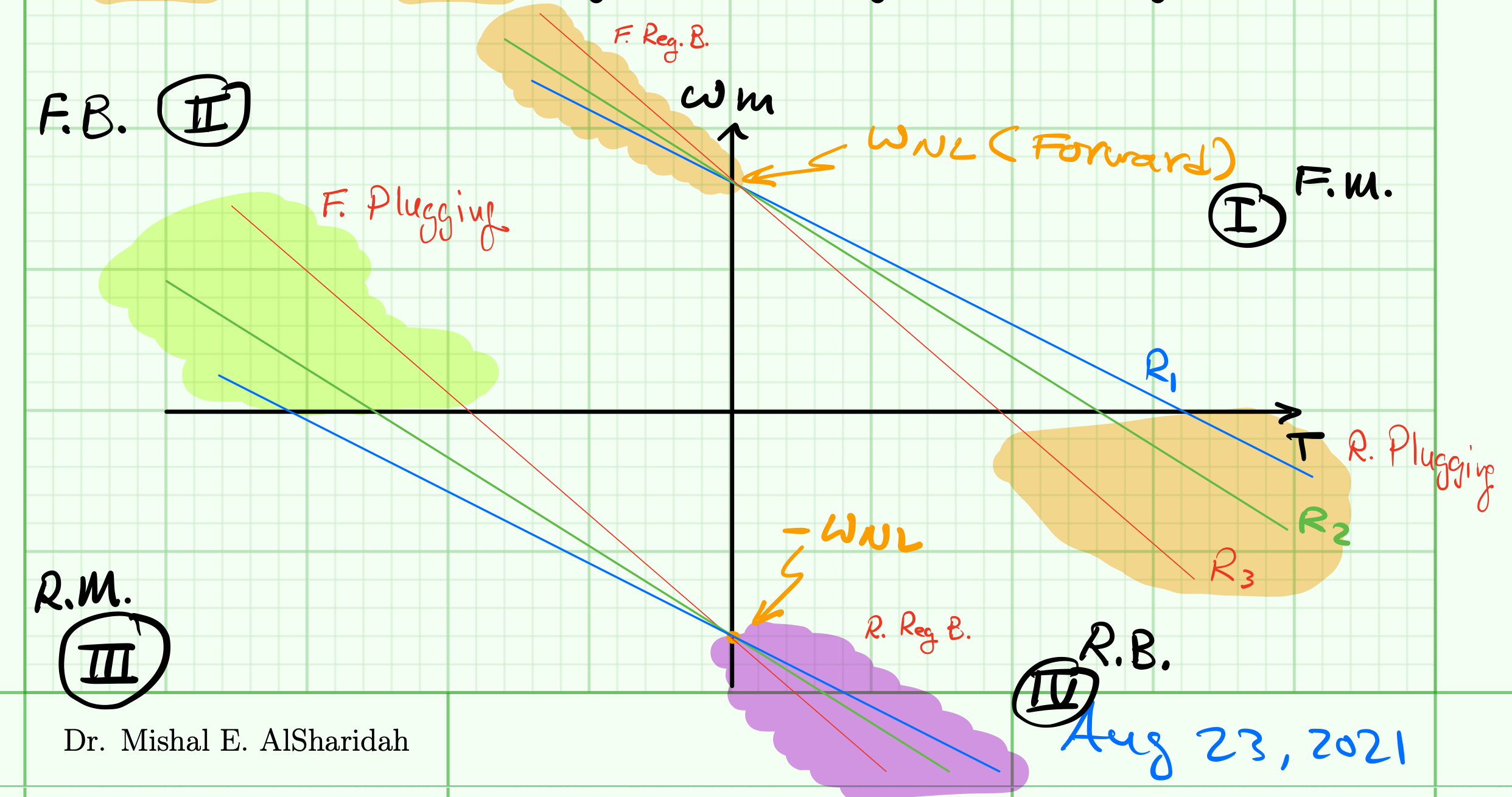
$P=T \cdot \omega_m$

  • if $P > 0$ power flow from PS to M
  • if $P < 0$ power flow from M to PS

    lecture-1-fig-1

Quadrant operation:

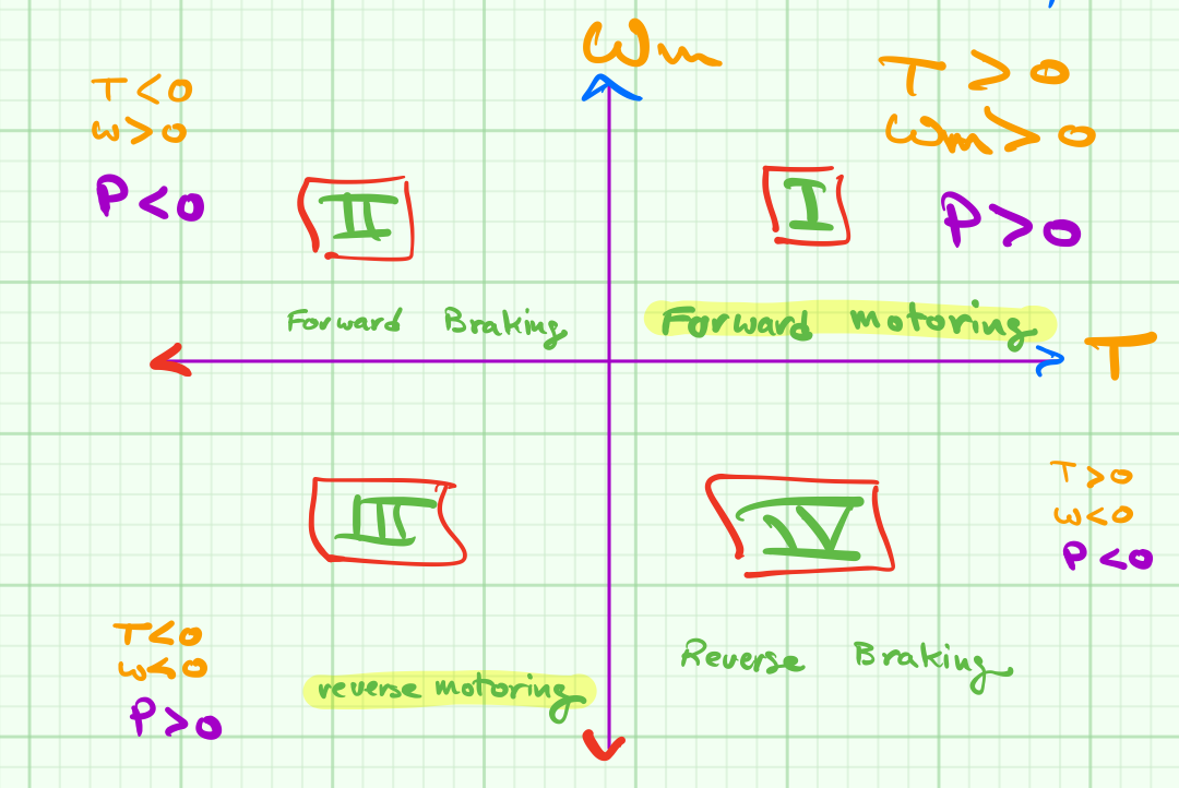
I : $T \gt 0$ & $\omega_m \gt 0$ $\longleftrightarrow$ forward motoring
II : $ T \lt 0 $ & $\omega_m \gt 0$ $\longleftrightarrow$ forward breaking
III: $T \lt 0$ & $\omega_m \lt 0$ $\longleftrightarrow$ reverse motoring
IV: $T \gt 0$ & $\omega_m \lt 0$ $\longleftrightarrow$ reverse breaking

Load torque

$$\begin{equation} T_L = T_F + T_L^*\end{equation}$$

where $ T_L^*$ is the physical load torque and $T_F$ is the motor friction torque.

what are the components of load torque ?

The friction torque \eqref{TF} is composed of a number of motor related frictions. Some are constant, some are short lived, and others related to speed.

$$\begin{equation}T_F = T_S + T_C + T_V + T_W\label{TF}\end{equation}$$

  • Static friction ($T_S$) - exists in static to low speed condition
  • Coulomb friction ($T_C$) - independent of speed
  • Viscous friction ($T_V$) - linearly proportional to speed
  • Windage friction ($T_W$) - proportional to the square of speed ($\omega^2$)
lecture-2-fig-1

Notes

2.2. Lecture 2: DC Motor Control

Stable operation of DC motor

During steady-state operation, The motor drives a load and speed will not vary at this stage. Constant speed means that there is no acceleration and $\frac{d\omega_m}{dt}=0$. Therefore:

$$T = J \frac{d \omega_m}{dt} + T_L $$

and hence, $T=T_L$, assuming the torque due to friction is zero for simplicity or that the load torque contains the useful load and friction values. To find out the operating point (Q), the operating point is defined by the intersection of the motor characteristic with the load characteristics. It means the motor will be running at the speed and the corresponding torque will be as shown in the figure below.

lecture-2-fig-4

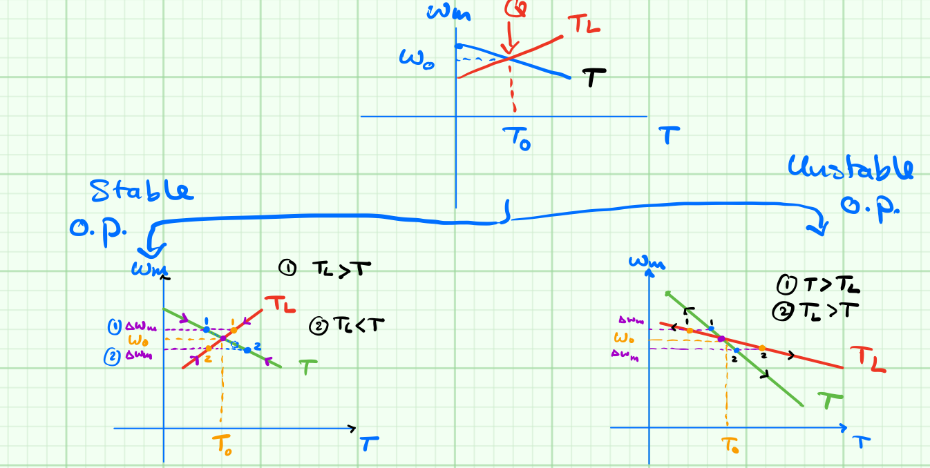
The condition for stable operation is $\frac{dT_L}{d\omega_m} \gt \frac{dT}{d\omega_m}$. Below is mathematical stability analysis proofing this condition.

$$T = T_L + J \frac{d\omega_m}{dt} \tag{a}\label{eq:a}$$

now in order to find out if the operting point Q in the figure above is stable, we perturb the torque by $\Delta T$ and monitor speed behaviour in small signal analysis sense.

$$\begin{align} T + \Delta T &= T_L + \Delta T_L + J \frac{d}{dt}(\omega_m + \Delta \omega_m) \tag{b}\label{eq:b}\\
\Delta T &= \Delta T_L + J \frac{d}{dt} \Delta \omega_m \tag{c} \label{eq:c}
\end{align}$$

Taking \eqref{eq:b} minus \eqref{eq:a} results in the small signal equation \eqref{eq:c}. Here we define of $\Delta T$ and $\Delta T_L$ are as follows:

$$\begin{align}\Delta T = \frac{dT}{d\omega_m} \cdot \Delta \omega_m \tag{d}\label{eq:d}\\
\Delta T_L = \frac{dT_L}{d\omega_m} \cdot \Delta \omega_m\tag{e}\label{eq:e}
\end{align}$$

substitution of \eqref{eq:d} and \eqref{eq:e} in \eqref{eq:c} yeilds

$$ \frac{dT}{d\omega_m} \cdot \Delta \omega_m = \frac{dT_L}{d\omega_m} \cdot \Delta \omega_m + J \frac{d}{dt} \Delta \omega_m \tag{f}\label{eq:f}$$

rearranging \eqref{eq:f} and solving for $\Delta \omega_m$

$$\begin{align}0 &= J \frac{d}{dt} \Delta \omega_m + \left [ \frac{dT}{d\omega_m} - \frac{dT_L}{d\omega_m} \right ] \tag{g}\label{eq:g}\\&\nonumber\\
\Delta\omega_m & = \Delta \skew{2}{\hat}\omega_m \cdot e^{-\frac{1}{J} \cdot \left [ \frac{dT}{d\omega_m} - \frac{dT_L}{d\omega_m} \right ]}\tag{h}\label{eq:h}\end{align}$$

where $\Delta\skew{2}{\hat}{\omega}_m$ is the initial condition of the motor speed.

$\Rightarrow$ if $t \rightarrow \infty$ then $\Delta\omega_m \rightarrow 0$ and accordingly $\left [ \frac{dT}{d\omega_m} - \frac{dT_L}{d\omega_m} \right ] \gt 0$ and the condition for steady-state is satisfied by \eqref{eq:i}

$$ \frac{dT_L}{d\omega_m} \gt \frac{dT}{d\omega_m} \tag{i}\label{eq:i}$$

Motoring and electric braking of Shunt/Sep. Excited DC motor

Motoring

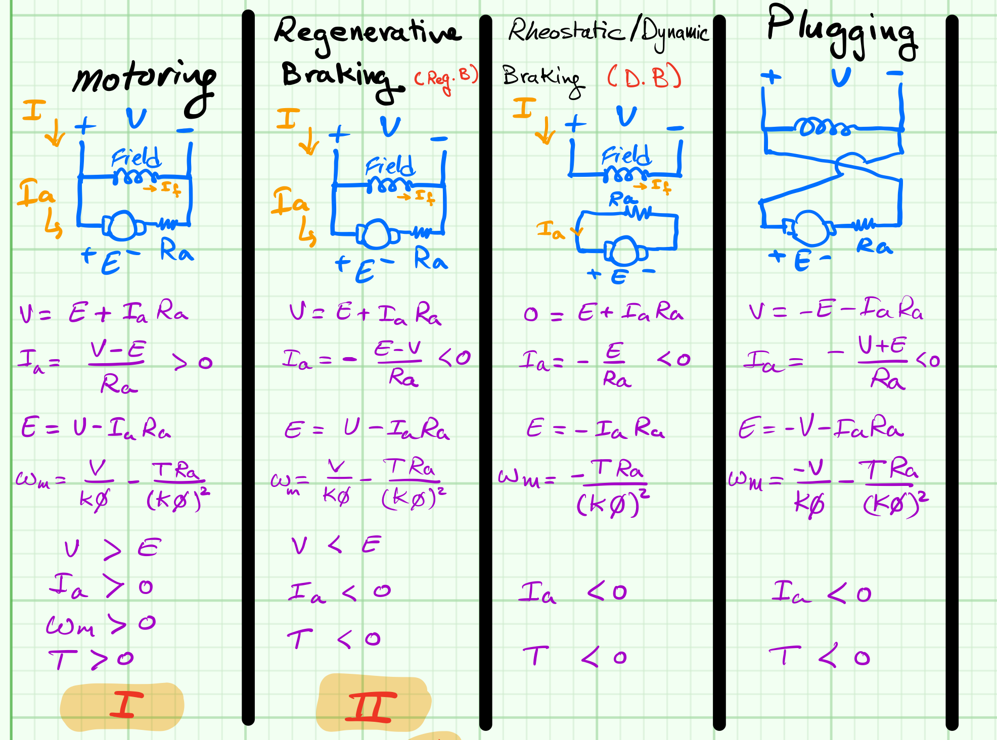
$$V=E+I_a R_a\tag{1}$$

$$I_a=\frac{V-E}{R_a}\tag{2} \gt 0$$

$$E=V-I_a R_a\tag{3}$$

$$\omega_m=\frac{V}{K\phi}-\frac{T R_a}{(K\phi)^2}\tag{4}$$

Condition:

  • $V\gt E$
  • $I_a\gt 0$
  • $T\gt 0$
  • $\omega_m\gt 0$

Re-generative braking

$$V=E+I_a R_a\tag{5}$$

$$I_a=-\frac{E-V}{R_a} \lt 0\tag{6}$$

$$E=V-I_a R_a\tag{7}$$

$$\omega_m=\frac{V}{K\phi}-\frac{T R_a}{(K\phi)^2}\tag{8}$$

Condition:

  • $V\lt E$
  • $I_a\lt 0$
  • $T\lt 0$

Dynamic/Rheostatic braking

$$0=E+I_a R_a\tag{9}$$

$$I_a=-\frac{E}{R_a}\lt 0\tag{10}$$

$$E=-I_a R_a\tag{3}$$

$$\omega_m=-\frac{T R_a}{(K\phi)^2}\tag{11}$$

Condition:

  • $I_a\lt 0$
  • $T\lt 0$

Plugging

$$V=-E-I_a R_a\tag{12}$$

$$I_a=-\frac{V+E}{R_a}\tag{13}\label{eq13}$$

$$E=-V-I_a R_a\tag{14}$$

$$\omega_m=-\frac{V}{K\phi}-\frac{T R_a}{(K\phi)^2}\tag{15}$$

Condition:

  • $I_a\lt 0$
  • $T\lt 0$
  • eq.\eqref{eq13}: $R_a$ has to be sufficiently high to avoid high current damage

Summary of motoring and electrical braking of Shunt/Sep. excited DC motor

lecture-2-fig-3

Quadrant operations

lecture-2-fig-2

Shunt motor T vs $\mathbf{\omega_m}$ plot


Notes

2.3. Lecture 3: Speed Control of DC Motor

Notes

2.4. Lecture 4: Induction Motor

Notes

2.5. Lab1: DC Motor Control - Part 1

MATLAB Simulink LAB 1 file

Matlab v2018a or above is required to run this file. Click the link below to download the file.

Note - ملاحظة :

  1. 1. عند تنزيل الملف تاكد من ان يكون اسم الملف خالي من الفراغات و الاقواس وعلامة الناقص
  2. 2. احفظ الفايل في ملف جديد ويكون اسم الملف خالي من الفراغات و علامة الناقص
  3. 3. "LAB1_HANDOUT_FILE_001v2.slx" تاكد من ان اسم الملف
  4. 4. تاكد من ان اسم الملف الكامل لا يحتوي على فراغات او اقواس او علامة الناقص

Step1: No load

  1. Run the simulation for a simulation time of 2 seconds with a constant DC voltage of 1V and no load torque.
  2. Assuming constant flux, when steady-state is reached, calculate motor parameters Ra, K PHI, and no load armature current.
  3. Record and plot Ia (A), speed (RPM), T (N.m), Load torque (N.m), and back EMF (V).
  4. Explain via plots and equations the behaviours of Ia, speed, motor torque and back EMF at the starting.

Step 2: Test load

  1. Run the simulation again for a simulation time of 2 seconds with a constant DC voltage of 1V and load torque of 8 N.m.
  2. Record in a table measurements of maximum Ia, maximum T, maximum speed, and maximum E.
  3. Calculate motor parameters Ra, K PHI, and no load armature current. Verify your findings with step 1.
  4. Record and plot Ia (A), speed (RPM), T (N.m), Load torque (N.m), and back EMF (V).
  5. Explain via commenting in the report on plots and equations the behaviours of Ia, speed, motor torque and back EMF.

Step 3: Variable DC voltage supply

  1. Run the simulation for a simulation time of 400 seconds.
  2. Remove the constant voltage supply block Vdc1 and connect the variable voltage supply Vdc2 and right click to uncomment.
  3. Record in a table measurements of maximum Ia, maximum T, maximum speed, and maximum E for every Vdc2 level.
  4. Create a table with the calculated motor parameters Ra, K PHI, and no load armature current for each Vdc2 level and Verify your findings with step 1 and 2.
  5. Record and plot Vdc2 (V), Ia (A), speed (RPM), T (N.m), Load torque (N.m), and back EMF (V).

Step 4: Rate limitter

  1. Run the simulation for a simulation time of 400 seconds.
  2. Connect and the rate limiter block between Vdc2 and the motor. Right click the block and uncomment to activate it.
  3. Record and plot Vdc (V), Ia (A), speed (RPM), T (N.m), Load torque (N.m), and back EMF (V).
  4. Explain via commenting in the report on plots and figures the behaviours of Ia, speed, motor torque and back EMF during Vdc2 change and during steady state.

Step 5: Variable load torque

  1. Run the simulation for a simulation time of 400 seconds.
  2. Remove TL1 and connect TL2. Right click TL2 and uncomment.
  3. Record and plot Vdc (V), Ia (A), speed (RPM), T (N.m), Load torque (N.m), and back EMF (V).
  4. Explain via commenting in the report on plots and figures the behaviours of Ia, speed, motor torque and back EMF during Vdc2 change and during steady state. Especially during motor speed changes.

Step 6: Constant speed operation

  1. Run the simulation for a simulation time of 400 seconds.
  2. When the motor speed reaches approximately 1800 RPM, adjust Vdc2 so that the motor maintains constant speed operation even during torque load changes.
  3. Record and plot Vdc (V), Ia (A), speed (RPM), T (N.m), Load torque (N.m), and back EMF (V).
  4. Explain via commenting in the report on plots and figures the behaviours of Ia, speed, motor torque and back EMF during Vdc2 change and during steady state. Especially during constant speed operation.

Step 7: Conclusion

Write, in your own words (arabic or english) about the experience and challenges during this lab experiment. Highlight the strog concepts aquired and mention any weaknesses. Suggest any improvement.


PDF version of the instructions

2.6. Lab 2: DCM Control - Part 2

MATLAB Simulink LAB 2 file

Matlab v2018a or above is required to run this file. Click the link below to download the file.

Note - ملاحظة :

  1. 1. عند تنزيل الملف تاكد من ان يكون اسم الملف خالي من الفراغات و الاقواس وعلامة الناقص
  2. 2. احفظ الفايل في ملف جديد ويكون اسم الملف خالي من الفراغات و علامة الناقص
  3. 3. "LAB1_HANDOUT_FILE_002v2.slx" تاكد من ان اسم الملف
  4. 4. تاكد من ان اسم الملف الكامل لا يحتوي على فراغات او اقواس او علامة الناقص

Step1: Measurements

  1. Set $\alpha$ to be $30^o$
  2. Create a table of initial measurements of $\alpha$, $\beta$, back EMF, $I_a$, $T$, and motor armature resistance and inductance.
  3. Calculate the value of Z
  4. Calculate the value of $K\phi$ from the torque equation.
  5. Verify the value of $K\phi$ using the back EMF equation.
  6. Calculate the percent error in $K\phi$. [error should not exceed 0.1%]

Step 2: back EMF verification

Verify the mesured back EMF value by using the back EMF equation

$$E=\frac{V_{m}(\cos \alpha-\cos B)}{(\beta-\alpha)} -\frac{R_a I_a}{(\beta-\alpha)} $$

  1. Calculate the percent error in E. If the error is larger than 2%, re-measure the angle $\beta$ so that the value of $V_a$ settles at the value of E and recalculagte the % error.

Step 3: $\beta$ verification

Using the equation below, verify that the value of $\beta$ satisfies the equality. If there is discrepancy, adjust $\beta$ so that the equation is satisfied within 0.1% error margin.
$$ 0=\frac{V_m}{Z} \sin (\beta-\theta)-\frac{E}{R_a}+\left[\frac{E}{R_a}-\frac{V_m}{Z} \sin (\beta-\theta)\right]\cdot e^{-(\beta-\alpha)\cot(\theta)} $$

  1. Using the new value of $\beta$, recalculate the back EMF.
  2. Using the new value of $\beta$, calculate $\omega_m$ using the following equation and compare with the measurement value by calculating the percent error.

$$ \omega_m=\frac{V_m(\cos \alpha-\cos \beta)}{k \phi(\beta-\alpha)}-\frac{T \cdot R_a\cdot \pi}{(K \phi)^{2}(\beta-\alpha)} $$

Step 4: Conclusion

Write, in your own words (arabic or english) about the experience and challenges during this lab experiment. Highlight the strog concepts aquired and mention any weaknesses. Suggest any improvement.

2.7. Lab 3: SP-FC-FWR fed DC Motor speed control

MATLAB Simulink LAB 3 file

Matlab v2018a or above is required to run this file. Click the link below to download the file.

Note - ملاحظة :

عند تنزيل الملف تاكد من ان يكون اسم الملف خالي من الفراغات و الاقواس وعلامة الناقص

  • Uncompress 'LAB3_SPEED_CONTROL_DC_MOTOR_ACDC.zip' into the MATLAB document folder.
  • Ensure to save the Lab 3 folder in the MATLAB folder and verify that the name of the folder does not contain invalid characters.


Introduction

In this experiment, the speed of the DC-motor is controlled by using an open-loop voltage control via firing angle $\alpha$ of the SCR based SP-FC-FWR and a closed loop speed control via speed and current PI control. The purpose of this experiment is to implement a close-loop speed control of a DC-motor drive. The standard 5HP DC-motor is used where its parameters are given in the motor block of the experiment. The controller will be tested on a simulation model of the DC-motor.


General questions

1) Explain two advantages of the Electric Drive System of the Electric motors?

2) A very important power electronic device is the Silicon Controlled Rectifier "SCR". Explain the construction, the function and the characteristics of the device.


  • Run the simulation (with default configuration parameters) for the following two cases. Compare the observed values with calculated values. Save the plots and include them in your report.

    • Case 1: Open-loop voltage control [Lab_3_SP_FC_FWR_DC_MOTOR_FOC_CASE1_v1.slx]
    • Case 2: Closed-loop speed control [Lab_3_SP_FC_FWR_DC_MOTOR_FOC_CASE2_v1.slz]
    • Adjust $\alpha$ to be between 0 and 179 degrees and observe the relationship with speed changes.
    • Set the load torque for CASE 1 to be
      Time=[0 3 6 9 12 15 18 21 24 27 30 33 36 39 42 45];
      TL=[2 4 6 8 10 12 14 16 18 20 22 24 26 28 30 32];
    • Set the reference speed for CASE 2 to be
      Time=[0 3 6 9 12 15 18 21 24 27 30 33 36 39 42 45];
      TL=[2 4 6 8 10 12 14 16 18 20 22 24 26 28 30 32];
      SPEED=100*[1 1 1 1 1 1 1 1 1 1 1 1 1 1 1 1];

Speed control of DC motor

  • Explaint the controller of the motor in more details and elaborate on control strategy structure flow and investigate the advantages and disadvantages of the PI controller method.
  • What is the power factor at rated speed? use the motor parameters and verify using the output mechanical power considering losses.
  • When changing alpha from 30, 60, 90, 120 and 150 degrees, record the speed of the motor for each case and calculate the related armature voltage and current assuming constant load of 20 N.m.
  • Change the reference speed to 800RPM by myliplying the speed vector by 8 as in

    SPEED=SPEED*8;

    Observe and compare the speed and torque ripple for both cases (100 rpm and 800 rpm), give an explanation for the differences.


Conclusion

In yout own words, write the advantages and benefits for adapting a speed controller. What are the limitations when implementing a SP-FC-FWR for DC motor speed control?

2.8. Lab 4: DC Chopper fed DC Motor Speed Control

MATLAB Simulink LAB 4 file

Matlab v2018a or above is required to run this file. Click the link below to download the file.

Note - ملاحظة :

عند تنزيل الملف تاكد من ان يكون اسم الملف خالي من الفراغات و الاقواس وعلامة الناقص

  • Uncompress 'LAB4_FOUR_QUAD_CHOPPER.zip' into the MATLAB document folder.
  • Ensure to save the Lab 4 folder in the MATLAB folder and verify that the name of the folder does not contain invalid characters.


Introduction

In Lab 3 experiment, motor speed control was achieved via a single-phase fully-controlled thyristor-based fullwave rectifier and speed control was demonstrated. In this Lab, the objectives are:
1) Observe the four-quadrant speed operation of a DC motor.
2) Control the speed of the DC motor and observe the effect of a stepped torque.


Tasks: (Open-Loop Control)

1) Save the waveform for the speed, torque, armature current and armature voltage label the quadrant of operation. [D_ref: 0.3, 0.6, 0.9; Torque: 20 N.m, -20 N.m]
2) Give a step change in load torque from 0 to 20 N.m (TL) at t = 1 s and note the resultant speed for each D_ref setting. Elaborate on the effect of changing D_ref.
3) Theoretically estimate the no-load speed value in rpm for each case
4) What is the net power supplied by the motor? What is the quadrant of operation for all the scenarios?


Tasks: (Closed-Loop Control)

1) Save the waveform for the speed, reference speed, torque, armature current and armature voltage label the quadrant of operation.
2) Give a step change in load torque from 0 to 20 N.m (TL) at t = 1 s and note the resultant speed.
3) Theoretically estimate the no-load speed value in rpm.
4) What is the net power supplied by the motor? What is the quadrant of operation?
5) repeat tasks 1-4 for all of the combinations of step torque and reference speed. [speed: 1000 rpm, -1000 rpm; Torque: 20 N.m, -20 N.m]


Speed control of DC motor

  • Explaint the controller of the motor in more details and elaborate on control strategy structure flow and investigate the advantages and disadvantages of the PI controller method.
  • What is the power factor at rated speed? use the motor parameters and verify using the output mechanical power considering losses.
  • When changing D_ref from 0.3, 0.6, 0.9 record the speed of the motor for each case and calculate the related armature voltage and current assuming constant load.
  • Compare the results of this experiment with the results from Lab 3 experiment, What are your observations and findings egarding the two methods?
  • Describe the advantages of this method of speed control.


Conclusion

In yout own words, write the advantages and benefits for adapting this speed controller. What are the limitations, if any, when implementing a four quadrant DC chopper for DC motor speed control?

2.9. MS Stream 52-270 Channel

Lectures and Labs on Microsoft Stream

3. Practice Questions

This chapter includes practice questions and problems that will assist in preparing for the midterm exam. Each set is of questions addresses material covered in the lectures, respectively. (i.e. set 1 $\rightarrow$ lecture 1)

3.1. Question Set 1

1) Which is the most efficient way of controlling a DC shunt motor below rated speed?

a. Armature resistance control

b. Armature voltage control

c. Field resistance control

d. Diverter resistance control in field circuit


2) Which of the following is an interface between Electric Power Supply and the motor?

a. Load

b. Sensing Unit

c. Power Modulator

d. Mechanical Gear


3) Fixed voltage Fixed Frequency AC can be converted to Variable Voltage Variable Frequency AC by:

a. AC voltage regulator

b. Cycloconverter

c. Fully controlled converter

d. Half controlled converter


4) Which of the following is called the inertial torque?

where $J$ is moment of inertia in $kg\cdot m^2$, B is the coefficient of viscous friction in $N\cdot m$/(rad/s) and $\omega_m$ is the rotor speed in rad/sec.

a. $J\cdot \dfrac{d\omega_m}{dt}$

b. $J\cdot \dfrac{d^2\omega_m}{dt^2}$

c. $B\cdot \omega_m$

d. $B\cdot \omega_m^2$


5) A motor drives two loads. One has rotational motion. It is coupled to the motor through a reduction gear with a=0.2 and efficiency of 95% . The load has moment of inertia of 5 $kg\cdot m^2$ and load torque of 20 $N\cdot m$. The other load has translational motion and has a weight of 500 kg which has to be lifted at a constant speed of 1 $\frac{m}{s}$. The coupling between the translational load and the motor has an efficiency of 90%. The motor inertia can be taken as 0.5 $kg\cdot m^2$ and the motor runs at a speed of 960 rpm. The equivalent inertia referred to the motor shaft is:

a. 0.54 $kg\cdot m^2$

b. 0.64 $kg\cdot m^2$

c. 0.74 $kg\cdot m^2$

d. 0.84 $kg\cdot m^2$


6) Given, $T_O=48.68$ N.m and $F_2=500$N The power developed by the motor in as is:

a. 3873 Watt

b. 4873 Watt

c. 5873 Watt

d. 6873 Watt


7) Which of the following Load Speed-Torque characteristics represents a hyperbola?

a. Fan type of load

b. Traction load

c. Low speed hoist load

d. Constant power load


8) Which of the following types of friction is independent of speed?

a. Coulomb friction

b. Static friction

c. Viscous friction

d. Windage friction


9) Which of the following load offers a constant load torque?

a. Traction load

b. Low speed hoist

c. Fan type of load

d. High speed hoist


10) A motor-load combination has the following speed torque characteristics:

$T = 100 - 0.1 \omega_m$ ($N\cdot m$)

$T_L = 0.05\cdot \omega_m$ ($N\cdot m$)

where T = motor torque in $N\cdot m$, $T_L$ = load torque in $N\cdot m$ and $\omega_m$ = speed of the motor-load combination in rpm. The steady state speed of the drive is:

a. 333.33 rpm

b. 455.55 rpm

c. 666.66 rpm

d. 721.66 rpm


11) A drive has the following motor and load speed-torque equation

Motor: $T=1+2\cdot \omega_m$

Load: $T_L=3\cdot \sqrt{\omega_m}$

The steady state equilibrium speeds are:

a. $1$ & $1/4$

b. $1$ & $1/2$

c. $2$ & $1/4$

d. $2$ & $1/2$


12) The drive in Q11 will operate in the steady state at a speed of:

a. $2$

b. $3/2$

c. $1$

d. $1/4$


13) What is the most appropriate way to smoothen the motor torque for a pulsating type load torque?

a. By connecting an inductance in series with the motor.

b. By connecting a flywheel with the motor-load combination.

c. By controlling the triggering angle of the converter feeding the motor.

d. By introducing a gear with appropriate gear ratio.


14) The motor torque speed characteristic is given by the equation $\omega_m= 100 - T$ where $\omega_m$ is in rad/sec and T is in $N\cdot m$. The initial motor torque is $10~N\cdot m$. A step load torque of $50~N\cdot m$ is applied at $t = 0$. If the total inertia of the motor load combination is $5~kg\cdot m^2$, the value of the motor torque after 5 sec is:

a. 50.0 $N\cdot m$

b. 45.2 $N\cdot m$

c. 35.2 $N\cdot m$

d. 25.2 $N\cdot m$


15) The speed of the motor in rad/sec in Q14 at t=5 sec is

a. 100 rad/s

b. 64.7 rad/s

c. 356.9 rad/s

d. 37.7 rad/s

3.2. Question Set 2

16) In which of the following control methods, the no-load speed of a shunt DC motor can be increased beyond rated value?

a. Armature resistance control

b. Armature voltage control

c. Field resistance control

d. Controlling resistance in parallel with armature


17) What is the ideal no-load speed for a series DC motor?

a. $V/(K\phi)$

b. $V/(K\phi)^2$

c. Zero

d. In finite


18) A 200 V , 11 A, 1500 rpm DC shunt motor has armature and field resistance of 0.5 $\Omega$ and 200 $\Omega$ respectively. The load torque can be assumed to be constant at rated value. What is the motor speed if a resistance of 5 $\Omega$ is inserted in the armature circuit?

a. 1115 rpm

b. 1222 rpm

c. 1328 rpm

d. 1404 rpm


19) A full controlled converter is feeding an R-L load with R = 10 $\Omega$ , L=31.83 mH. If the input frequency is 50 Hz, the impedance angle ($\theta$) of the load is

a. $30^o$

b. $45^o$

c. $60^o$

d. $75^o$


20) For Q19, if the input voltage is 230 V / 50 Hz and $\alpha=30^o$. What is the average output voltage assuming continuous conduction?

a. 149V

b. 169V

c. 179V

d. 189V


21) A 230 V , 50 $H_Z$ single phase supply feeds a fully controlled FWR. The FWR is used to power the armature of a separately excited DC motor. The DC motor ratings are 200 V , 10 A (armature current), 1000 rpm, $R_a$ = 1 $\Omega$. The no-load speed of the motor supplied from the FWR is

a. 179 rad/s

b. 169 rad/s

c. 159 rad/s

d. 129 rad/s


22) Discontinuous current operation for a SP-FC-FWR fed separately excited DC motor occurs for speeds

a. Higher than the critical speed

b. Lower than the critical speed

c. Higher than 50% of the critical speed

d. Lower than 50% of the critical speed


23) Extinction angle($\beta$) for a SP-FC-FWR can be calculated by

a. A closed form solution of the relevant equation

b. An iterative solution of the relevant equation

c. Computation of no load speed of the motor

d. Computation of converter output voltage


24) During coasting period in a SP-FC-FWR, the armature voltage is

a. The same as input ac voltage

b. The same as the drop across the armature inductance

c. The same as the armature back-EMF

d. The same as the drop across the armature resistance


25) In which of the following methods, the supply voltage to the armature of a separately excited DC motor is reversed?

a. Forward motoring

b. Forward regenerative braking

c. Forward dynamic braking

d. Forward plugging


26) For a semi-controlled converter fed DC motor, what is the region for $\pi \lt \omega t \lt \beta$ called?

a. Duty interval

b. Coasting interval

c. Freewheeling interval

d. Zero-current interval


27) A 200 V , 900 rpm, 100 A separately excited DC motor has an armature resistance of 0.05 $\Omega$. It is fed by SP-FC-FWR supplied by an ac voltage of 230 V, 50 $H_Z$. Assuming continuous conduction, calculate the firing angle for rated motor torque and 900 rpm speed.

a. $75^o$

b. $65^o$

c. $30^o$

d. $15^o$


28) For Q27, calculate the motor speed for rated torque and $\alpha=60^o$.

a. 861.2 rpm

b. 746.5 rpm

c. 505.9 rpm

d. 454.7 rpm


3.3. Question Set 3

29) A half controlled converter can operate in how many quadrants of V-I plane?

a. One

b. Two

c. Three

d. Four


30) For a semi-controlled rectifier, the duration $\pi \lt \omega t \lt \beta$ is known as

a. Duty Interval

b. Coasting Interval

c. Freewheeling Interval

d. Zero-Current Interval


31) A 220 v , 960 rpm, 10A separately excited DC motor has an armature resistance of 2$\Omega$. It is fed from a SP-SC-FWR with an input AC supply of single phase 230 V rms, and 50 Hz. If the triggering angle $\alpha = 60^o$, the no load speed of the motor is

a. 960 rpm

b. 1029 rpm

c. 1423 rpm

d. 1561 rpm


32) If the triggering angle $\alpha = 120^o$ for Q31, the no-load speed of the motor is

a. 960 rpm

b. 1051 rpm

c. 1352 rpm

d. 1529 rpm


33) A SP-FC-FWR is used to control the armature of a separately excited DC motor. The critical speed which separates continuous and discontinuous current operation is found out to be 720 rpm. Which of the following statements is correct?

a. The converter operates in continuous current operation for speed greater than 720 rpm

b. The converter operates in continuous current operation for speed less than 720 rpm

c. The converter operates in continuous current operation for speed greater than 360 rpm

d. The converter operates in continuous current operation for speed less than 360 rpm


34) If the AC input supply frequency is $f$ , the ripple frequency of the output voltage of a three-phase fully controlled rectifeir is

a. $f$

b. $2 f$

c. $3 f$

d. $6 f$


35) A three phase fully-controlled rectifier is fed from three-phase, 400 V 50 $H_Z$ AC supply. If the triggering angle of the converter is $45^o$, the average output DC voltage is

a. 231. 1 V

b. 305.6 V

c. 381.9 V

d. 421.7 V


36) A three-phase fully-controlled rectifier is feeding the armature of a separately excited DC motor. The motor has to operate in quadrant III. Which of the following methods is suitable?

a. By adjusting the triggering angle $\alpha$ only.

b. By adjusting the triggering angle $\alpha$ followed by armature connection reversal.

c. By operating with triggering angle $\alpha \gt 90^o$.

d. By connecting a freewheeling diode across the armature in addition to adjusting the triggering angle $\alpha$.


37) A class A two-quadrant chopper operates in which quadrants of V-I plane?

a. 1 & 2

b. 2 & 3

c. 3 & 4

d. 4 & 1


38) A 230 V , 900 rpm, 200 A separately excited DC motor has an armature resistance of 0.05 $\Omega$. The motor is fed from a two quadrant chopper which provides motoring and regenerative braking operation. The source has a voltage of 200 VDC. Assuming continuous conduction , calculate the duty cycle of the chopper for operation at rated torque and speed of 500 rpm.

a. 0.54

b. 0.44

c. 0.34

d. 0.24


39) The motor in Q38 is operated in regenerative braking mode with rated torque and speed of 600 rpm. Calculate the duty cycle of the switch.

a. 0.29

b. 0.39

c. 0.49

d. 0.59


40) Assuming continuous current operation for a single quadrant chopper used for motoring operation of a DC motor, what is the interval $t_{on} \lt t \lt T$ called?

a. Duty interval

b. Freewheeling interval

c. Coasting interval

d. Energy storage interval


3.4. Question Set 4: Induction Motor

41) A 3-phase, 50 Hz, 4 pole induction motor at a speed of 1400 rpm. The slip of the motor is

a. 0.023
b. 0.034
c. 0.066
d. 0.072


42) The rotor of an induction motor carries

a. No conductors
b. Open circuited conductors
c. Short circuited conductors
d. A solid iron core


43) A 4 pole, 50 Hz star connected induction motor is supplied with square wave voltage from an inverter. The motor rotates at a speed of 1425 rpm. The slip of the motor with respect to 5th harmonic field is

a. 1
b. 1.05
c. 1.13
d. 1.19


44) The slip of the motor in Q43 with respect to 7th harmonic field is

a. 0.75
b. 0.86
c. 0.95
d. 1


45) The average torque due to harmonic voltages is

a. quite significant and it adds to the fundamental torque
b. quite significant and it subtracts from the fundamental torque
c. quite insignificant
d. pulsating in nature


46) An unbalance is created in the rotor circuit of an induction motor which is started from rest. The motor speed will settle down to

a. a value close to half the synchronous speed
b. a value close to the synchronous speed
c. a value close to one fourth of the synchronous speed
d. a value close to zero


47) A 400 V. 50 Hz, 4 pole, 1440 rpm induction motor has following parameters:

\(R_s = 1.5 \Omega\) , \(R'_r = 0.4 \Omega\) , \(X_s = X'_r = 1.2 \Omega\) , \(Xm = 50 \Omega\)
The peak value of the motoring torque, \(T
{max}\), of the motor is
a.142.4 N.m
b. 165.3 N.m
c. 172.5 N.m
d. 192.3 N.m


48) What is the effect of unbalanced voltage on the operation of induction motor?

a. It results in reduced torque and reduced power
b. It results in reduced torque but rated power
c. It results in rated torque but reduced power
d. It results in zero torque and zero power


49) A three phase induction motor was running in steady state with a slip of s=0.04. One of the motor phases got open circuited. Assuming the speed change to be insignificant, the slip of induction motor with respect to the reverse rotating field is

a. 0.04
b. 0.96
c. 1.04
d. 1.96


50) For regenerative braking of induction motor

a. Synchronous speed should be a little higher than the rotor speed
b. Synchronous speed should be a little lower than the rotor speed
c. Synchronous speed should be doubled
d. Synchronous speed should be increased by a factor of 1.5


51) A star connected induction motor is fed from a square wave inverter. The rms values of various harmonic components of the stator current are the following:

$I_s^{1st} = 10 A $ , $ I_s^{5th} = 3 A $ , $ I_s^{7th} = 1.5 A $
Harmonics higher than 7th harmonic can be neglected. The rms value of the total stator current is
a. 10A
b. 10.31 A
c. 10.54 A
d. 14.5 A

52) Plugging of induction motor involves

a. Increase of synchronous speed
b. Decrease of synchronous speed
c. Reversal of the phase sequence of the stator
d. Increase of the stator voltage magnitude


53) A delta connected three phase induction motor is supplied from a square wave 3-phase inverter. Which of the frequency components of current will flow in the stator phases?

a. 1,2,3,4,5,..
b. 1,5,7,11,13,..
c. 1,3,5,7,9,..
d. 2,4,6,8,10...